Superconducting Quantum Hardware Design and Analysis
Design tools
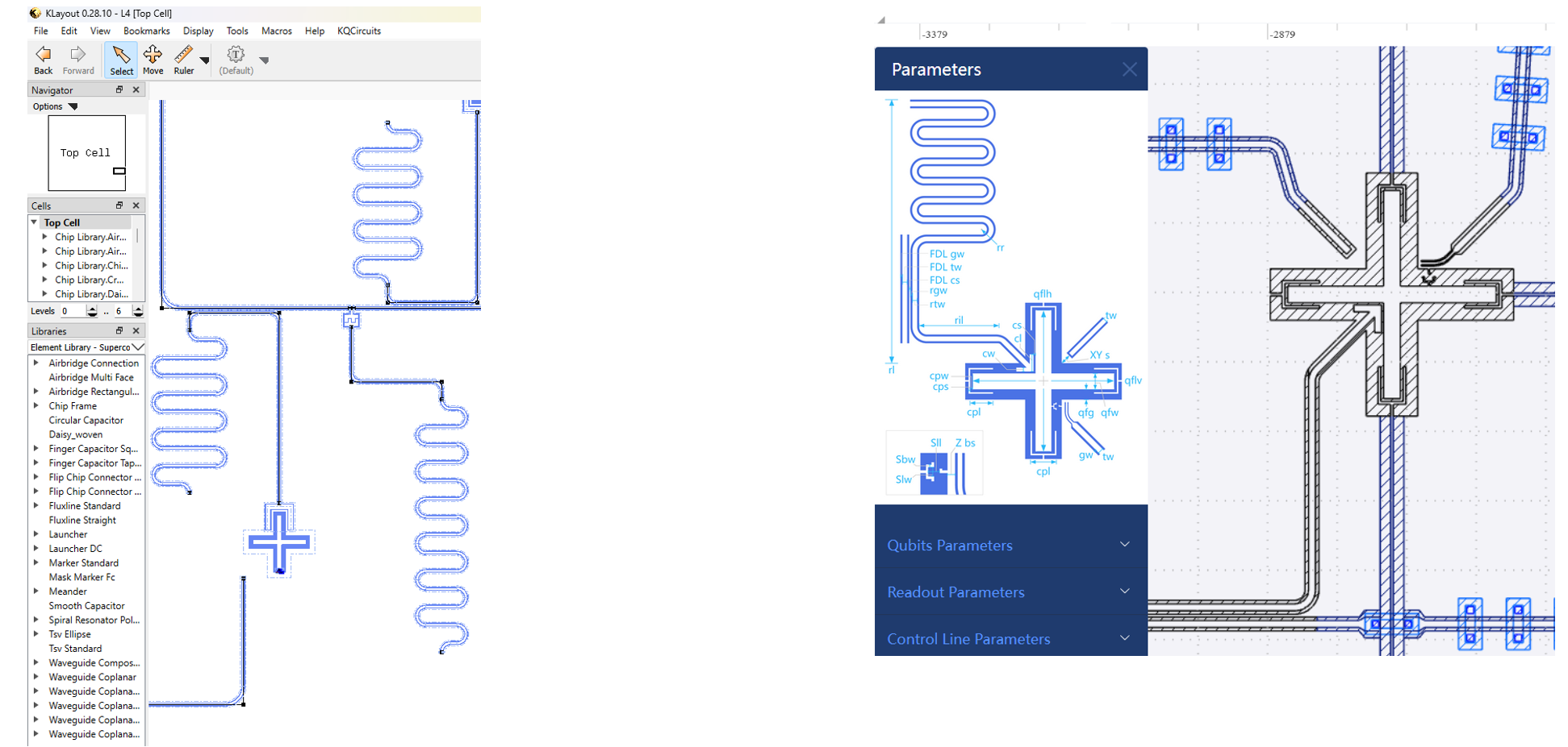
For layout design
As illustrated in Fig. 1, layoutting design focuses on the placement of the superconducting qubits and their interconnections such as the coupling resonators. While technically the designs are possible to be done directly through KLayout to generate the gds files, it is more convenient to use dedicated tools such as IBM Qiskit Metal [1], IQM KQCircuits [2] and SpinQ QEDA [3] to help with the layoutting. Users can use the Python interface to specify the locations and sizes of the components, and export the design to gds files for fabrication.
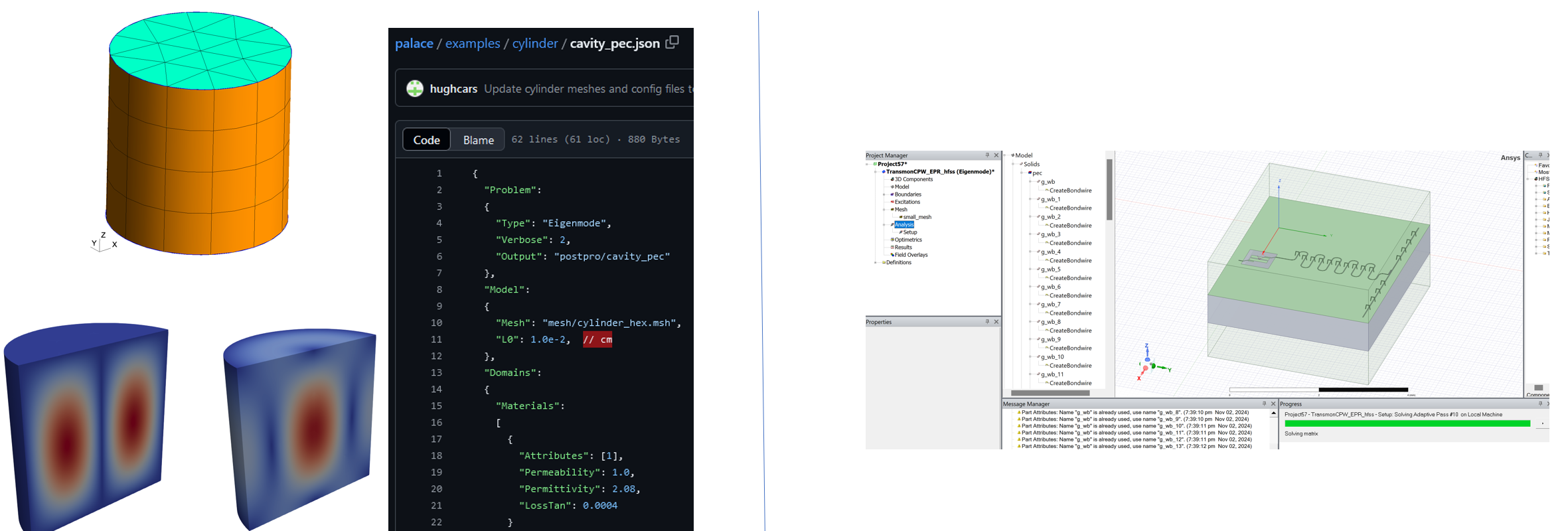
For simulation or analysis
After the layout design is complete, the design can be imported to simulation or analysis software such as AWS Quantum Palace [4], ANSYS Electronics [5] to perform electromagnetic simulation and circuit analysis. An example of the analysis software is shown in Fig. 2. These software can help to extract the circuit parameters such as the capacitance and inductance values, which can be used to calculate the qubit frequencies, anharmonicities, and coupling strengths. Using the convention used in ANSYS, we can divide the analysis into three types, namely the Q3D, driven-mode, and eigenmode analysis. While Q3D analysis extracts the Maxwell capacitance matrix among the conductors (or superconductor after being cooled), driven-mode analysis excites the circuit through an input and output fashion. On the other hand, the eigenmode analysis obtains the resonance frequencies of the circuit by solving the electromagnetic field in the system.
While open-source frameworks like Qiskit Metal or KQCircuit are more modularized, some commercial software like Keysight Quantum Pro [6] combines both layout design and analysis, providing a more integrated solution for superconducting quantum circuit design.
For circuit analysis
Lumped Oscillator Model
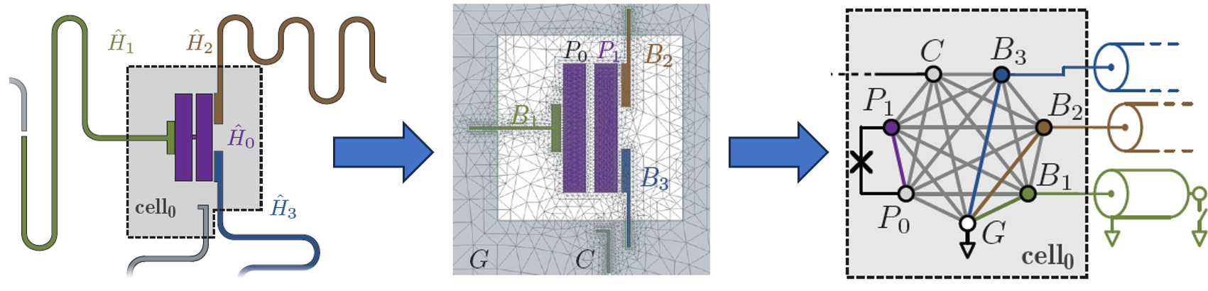
The Lumped oscillator Model (LOM) analysis [7, 8] uses the Maxwell Capacitance Matrix calculated by the static Q3D analysis. This matrix is defined according to the superconductor plates according to the geometry of the components like transmon qubit. One can then isolate each subsystem (Fig. 3) while constructing the Hamiltonian \(H_n = \frac{1}{2} \hat{Q}_n C_n^{-1} \hat{Q}_n + \frac{1}{2} \hat{\Phi}_n L_n^{-1} \hat{\Phi}_n + \sum_{j \in \mathcal{J}} \epsilon_j(\hat{\Phi}_j)\). Combined with the circuit quantum electrodynamics [9], Qiskit Metal [1] has implemented this analysis method to obtain the estimate of frequency, anharmonicity, coupling strength, \(T_1\), and \(T_2\).
Black-box quantization (BBQ) / Impedance Analysis
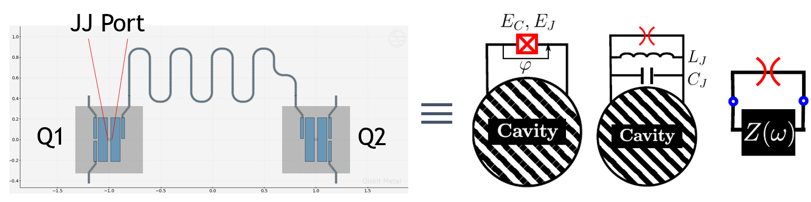
The impedance-based Black Box Quantization (BBQ) [10, 11] uses the result from the HFSS Driven Modal Analysis. With the JJ of interest as the excitation port, one can simulate the circuit to obtain the self-scattering \(S(\omega)\), admittance \(Y(\omega)\), and impedance \(Z(\omega)\) response. With the admittance \(Y(\omega) = Z^{-1}(\omega) = j\omega C_p + \frac{1}{j\omega L_p} + \frac{1}{R_p}\), one can calculate the RLC values at the poles of impedance or zeros of admittance. Based on this, we can also estimate the frequency, Q factor, and anharmonicity, along with the coupling factor.
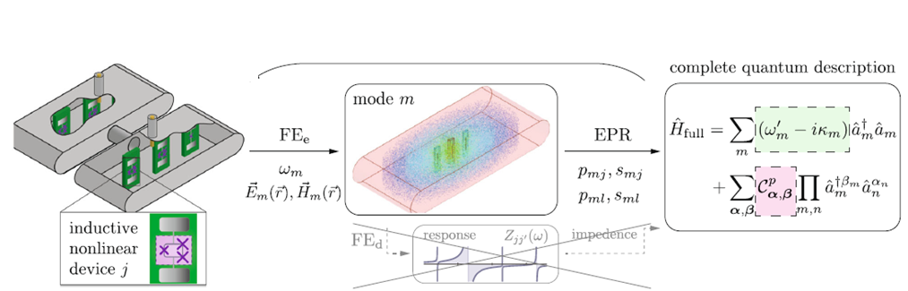
Energy Participation Ratio (EPR)
The most recent analysis method uses the Energy Participation Ratio (EPR) obtained based on the HFSS Eigenmodal analysis [12]. From the classical EM simulation, we can calculate the EPR value which is the ratio between the inductive energy stored in the considered JJ element and the total inductive energy stored during the corresponding eigenmode. \cite{iEPR} suggests its inductive EPR (iEPR) [13] to be the ratio of the inductive energy stored in the whole element for better accuracy. By having the EPR \(p_{(q,c)}\), we can find the quantum zero-point fluctuation \(\phi^2_{(q,c)} = p_{(q,c)} \frac{\hbar \omega_{(q,c)}}{2E_J}\), and thus bridge with the JJ reduced flux \(\hat{\phi_J}= \phi_q(\hat{a}_q + \hat{a}^\dagger_q) + \phi_c(\hat{a}_c + \hat{a}^{\dagger}_c)\). Frequency can then be calculated along with the Kerr matrices based on the EPR values.
References
[1] https://qiskit-community.github.io/qiskit-metal/
[2] https://iqm-finland.github.io/KQCircuits/
[3] https://www.spinquanta.com/products-services/qpu-eda-design-software
[4] https://awslabs.github.io/palace/stable/
[5] https://www.ansys.com/products/electronics
[6] https://www.keysight.com/de/de/lib/resources/miscellaneous/eda-software/quantum-eda.html
[7] ZK Minev et al, Circuit quantum electrodynamics (cQED) with modular quasi-lumped models, http://arxiv.org/abs/2103.10344, 2021
[8] Y Liu et al, Design of interacting superconducting quantum circuits with quasi-lumped models, APS March Meeting 2022
[9] A Blais et al, Circuit quantum electrodynamics, Rev. Mod. Phys. 93, 025005 (2021)
[10] SE Nigg et al, Black-Box Superconducting Circuit Quantization, Physical Review Letters 108, 240501 (2012)
[11] F Solgun et al, Blackbox quantization of superconducting circuits using exact impedance synthesis, Physical Review B 90, 134504 (2014)
[12] ZK. Minev et al, Energy-participation quantization of Josephson circuits, npj Quantum Information 2021
[13] K-H Yu et al, Using inductive Energy Participation Ratio for Superconducting Quantum Chip Characterization, Physical Review Applied 21, 034027 (2024)
Enjoy Reading This Article?
Here are some more articles you might like to read next: